An icosahedron on HDMI, drawn by a TxHDL core
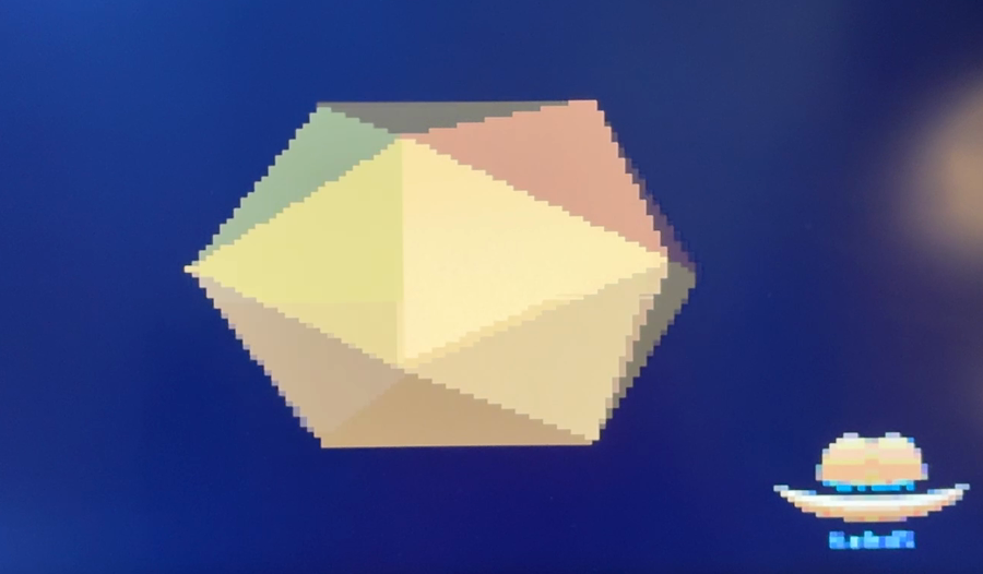
tl;dr: A RISC-V core written in TxHDL draws a turning icosahedron on a monitor, with the TxHDL logo in the corner. Watch it at https://youtu.be/YbHtntvvydk. The whole thing, core, memory, video, Ethernet and a serial loader, is one bitstream in the board’s flash, and the program that draws is 560 lines of Rust that go down the serial port in about a second. Read on for how it is put together.
What you are looking at
The board is an Alinx AX7A200B, with an Artix-7 200T on it. The core is Vreteno, an RV32IMC that I wrote in TxHDL together with Dragiša Janković. If you have not seen TxHDL before: you write the hardware as a Rust program, and the Verilog, the simulation and the checks all fall out of a Rust library and a few macros. I wrote a whole post about it if you want the long version.
Everything in the diagram below that computes is lowered from Rust. The only Verilog I wrote by hand is the top of the design: clocks, resets, pins, and a handful of FIFOs that carry signals between clocks. That’s it.
Here’s how it works
Place and route of this design takes about half an hour. If the program the core runs were baked into the netlist, every change to the picture would cost me half an hour, and I have better things to do with half hours. So the core does not come up running a program. It comes up running a small loader in its boot memory. The loader waits on the serial port, takes a program, writes it into the DDR3 memory and jumps to it. The hardware stays put. The software is whatever I sent last.
The core talks to the video peripheral through a third slot on the
page at 0x3000, next to the serial port and the pulse width
modulator (yes, there’s one of those too, it fades an LED). The
interesting bit about that slot: the video peripheral runs on the
pixel clock, 25.2 MHz, while the core runs at 100 MHz, and a VGA
raster at 100 MHz would be a mess. So the slot leaves the lowered
design as five channel ports, and each of the five AXI-Lite channels
crosses to the pixel clock through its own asynchronous FIFO, with
Gray-coded pointers, the same FIFO the Ethernet port uses. The five
channels have no timing relationship to each other, which is why
crossing each one on its own is all that’s needed.
The video peripheral: three registers and a cursor
The peripheral is three words on the bus, and I quite like how little that is.
Writing the pixel word puts a colour at the cursor and moves the cursor one column to the right. So a run of pixels along a scanline is one write of the cursor and then one write per pixel, and the whole screen is one write of the cursor and 19 200 writes of the pixel word. Each framebuffer pixel is four by four screen pixels, a colour is twelve bits, four each of red, green and blue, and there is exactly one framebuffer. Keep that last one in mind, it shapes the drawing.
Sending the program down the wire
The loader speaks a small protocol. Every number is four bytes, least significant byte first.
The K after every word is there because the serial port on the core
buffers eight bytes, and a sender that streams without waiting
overruns it right away. Waiting for a K per word costs about a
second for the 2 500 words of this program. Build, send, watch. That’s
the loop, and it is the reason the whole flagship exists.
If you want the board back in the loader without reprogramming it, you hold the serial line low for 30 ms (one zero byte at 300 baud does it) and the top resets the core. Or press the RESET key. Either way the memory keeps running and the loader is listening again.
Drawing the thing
The solid
An icosahedron has twelve vertices and twenty faces. The vertices are
the corners of three golden rectangles: (0, ±1, ±φ) and its two
cyclic rotations, where φ is the golden ratio.
I did not type the faces in. The program works them out from the
vertices at startup and tells me how many it found, which is a nice
sanity check to have for free. All the arithmetic is fixed point,
ten fractional bits in an i32, because the core has no floating
point, and a sine is a 65-entry quarter-wave table read forwards,
backwards and negated.
One number does two jobs
The face normals are made unit vectors once and turned with the solid.
The light sits at the viewer’s eye, so the z component of a turned
normal is the cosine between the face and the viewer.
A face is visible exactly when that number is positive, and how bright it is drawn is that same number. The solid is convex, so a face that faces you is never behind another one, and there is no depth buffer. Convexity is doing real work here. The eye sits eight radii from the solid, which is close enough that the near faces are visibly larger than the far ones and far enough that they don’t balloon.
Every pixel written exactly once
There is one framebuffer, and the raster reads it while the core writes it. Anything written twice within a frame can be seen in between, so I don’t clear the screen and draw on it. Instead a row is composed in a small buffer, the background, the spans of the faces and the logo together, and then written to the framebuffer once, left to right.
The faces that pass the normal test tile the silhouette of a convex solid without overlapping, so a row is a set of disjoint spans on a background, and one pass can write it. Edges are interpolated in Q16 with a half-open fill rule, so two faces that share an edge paint each pixel of it exactly once, with no crack and no overlap. Nice side effect: half the writes of a clear-then-draw scheme are gone, and so is the flicker they would cause.
The colours
The solid is drawn in the tan of the hat in the logo. Twelve bits of colour is not a lot, so a face’s brightness is one of sixteen steps on a single ramp of that one tan, spaced by a square root so the steps look evenly spaced to the eye, with a floor of two fifths so no face goes near black. Between two steps, a two by two ordered dither.
The dither quadruples the levels the eye sees, at the cost of a fine checker on the face that you can spot up close and cannot from a chair. With it the solid turns rather than steps, and I’m happy with how it looks.
Where it landed on the chip
Since I had the routed design anyway, I had Vivado tell me where each subsystem ended up. Every placed cell is attributed to a subsystem by the top-level instance it sits under, counted per slice column and row, and drawn.
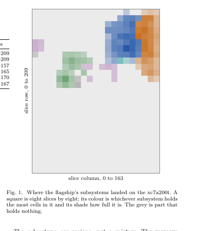
The memory controller (orange) holds the right edge against the memory’s bank, the core (blue) sits next to it, the Ethernet (green) is between its PHY pins and the core, and the video (purple) is a few patches on the left near the encoder’s pins. Nobody told the placer any of this. Logic goes where its pins are, and where the thing it talks to is. The whole flagship uses 8 per cent of the part, so there is room for a lot more.
What’s next
A moving edge can still tear where the raster and the writer cross, because there is one framebuffer; a second one fixes that. There is no depth buffer, because a convex solid does not need one; the next solid will. And the Ethernet port is on the core’s bus now, so the next demo gets to talk to the network.
The code is in the TxHDL repository: the program is
cpu/vreteno/rust/ico_hdmi.rs, the video peripheral is
lib/parts/src/hdmi.rs, the board top is flagship/board/flagship.v,
and the document on the flagship, placement map included, is built by
//docs:flagship.